General Information on Thermocouples – Basics & Types

Basics of Thermocouples: Construction, Operation, and Thermocouples According to ISO EN 60584-1. An Overview of Types S, R, B, K, J, N, T, E, and L.

General Information

Thermocouples are sensors used to measure temperature. The main components of thermocouples are a thermocouple element, which generates what is known as thermoelectric voltage, and a connector, such as a plug. Thermocouples are used in many areas of temperature measurement. They are characterized by their highly flexible design and fast response time.

Overview of Thermocouples

The following thermocouples are defined in ISO EN 60584-1:

Specifications
TypePositive Connection
[plus]
Negative Wire
[minus]
Color DIN
[plus / minus]
Temperature range
[°C]
JCuNiFriblack / white-200 +750
KNiCrNiAlgreen / white-200 +1100
NNiCrSiNiSipink / white-200 +1200
SPtRh10%Ptorange / white0 +1600
RPtRh13%Ptorange / white0 +1600
BPtRh30%PtRh6%gray / white+600 +1700
CWRe25%WRe5%red / white0 +2200

Various combinations of metals and alloys have proven to be advantageous because they exhibit an almost linear relationship between stress and temperature.

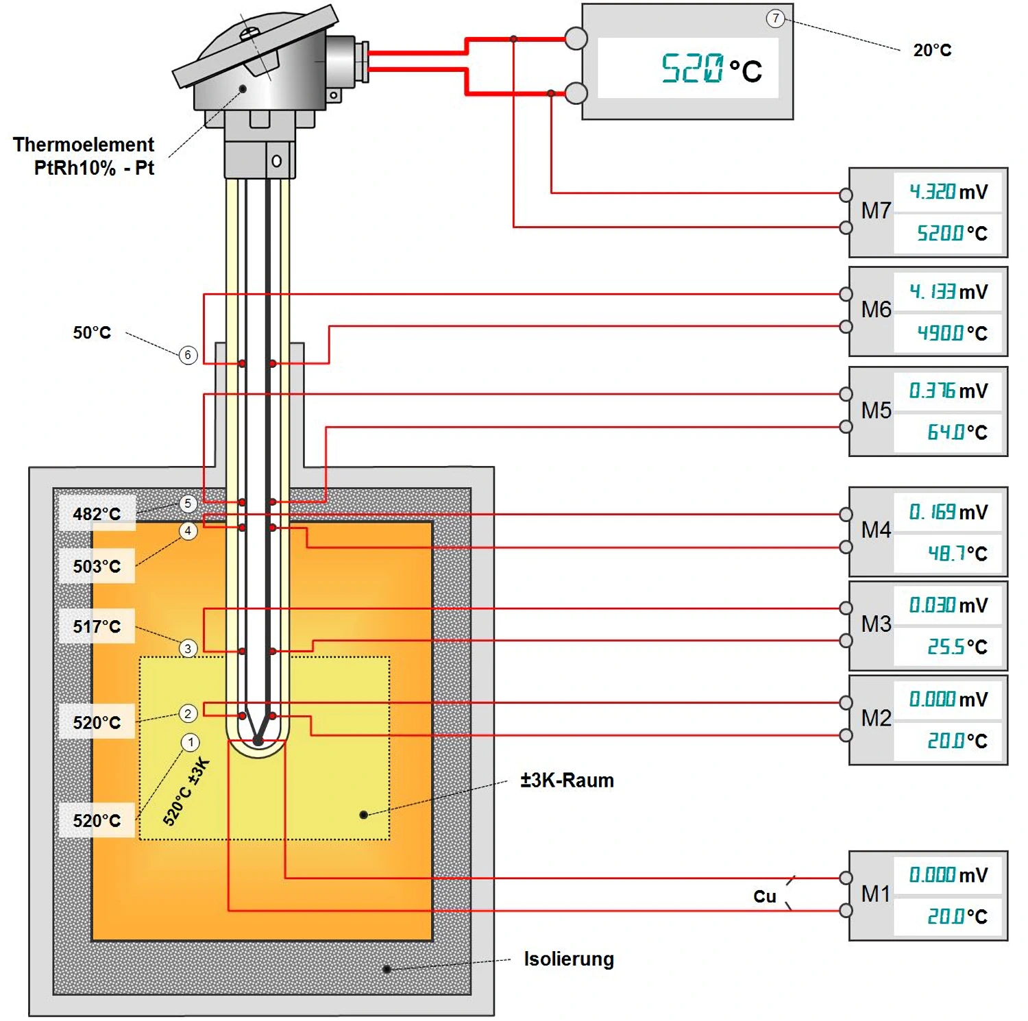
It is important to know that the thermoelectric voltage does not originate at the tip. The voltage is generated between the two wires. Most of the stress occurs in the area where the temperature difference is greatest, for example, at the transition from the furnace chamber to the insulation.
Thermal stress

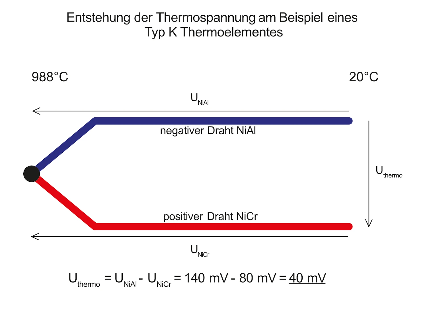
A thermocouple consists of two wires made of different alloys. Each of these wires generates a specific voltage as soon as one end is warmer than the other. When the two wires are connected, the difference in voltage between them can be measured. This difference is called thermoelectric voltage.

How exactly is thermoelectric voltage generated?

Every electrical conductor contains free electrons. They can move within the conductor, thereby enabling, for example, an electric current to flow.

In very simplified physical terms, these free electrons occupy a certain amount of space, which increases with temperature.

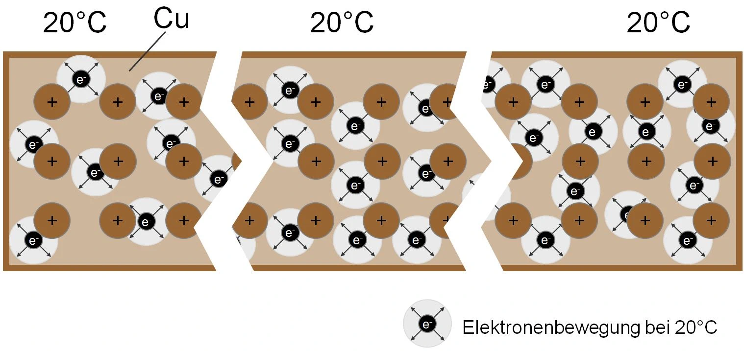
In a uniformly heated copper conductor, this region is approximately the same size. This is shown schematically in Figure 1.

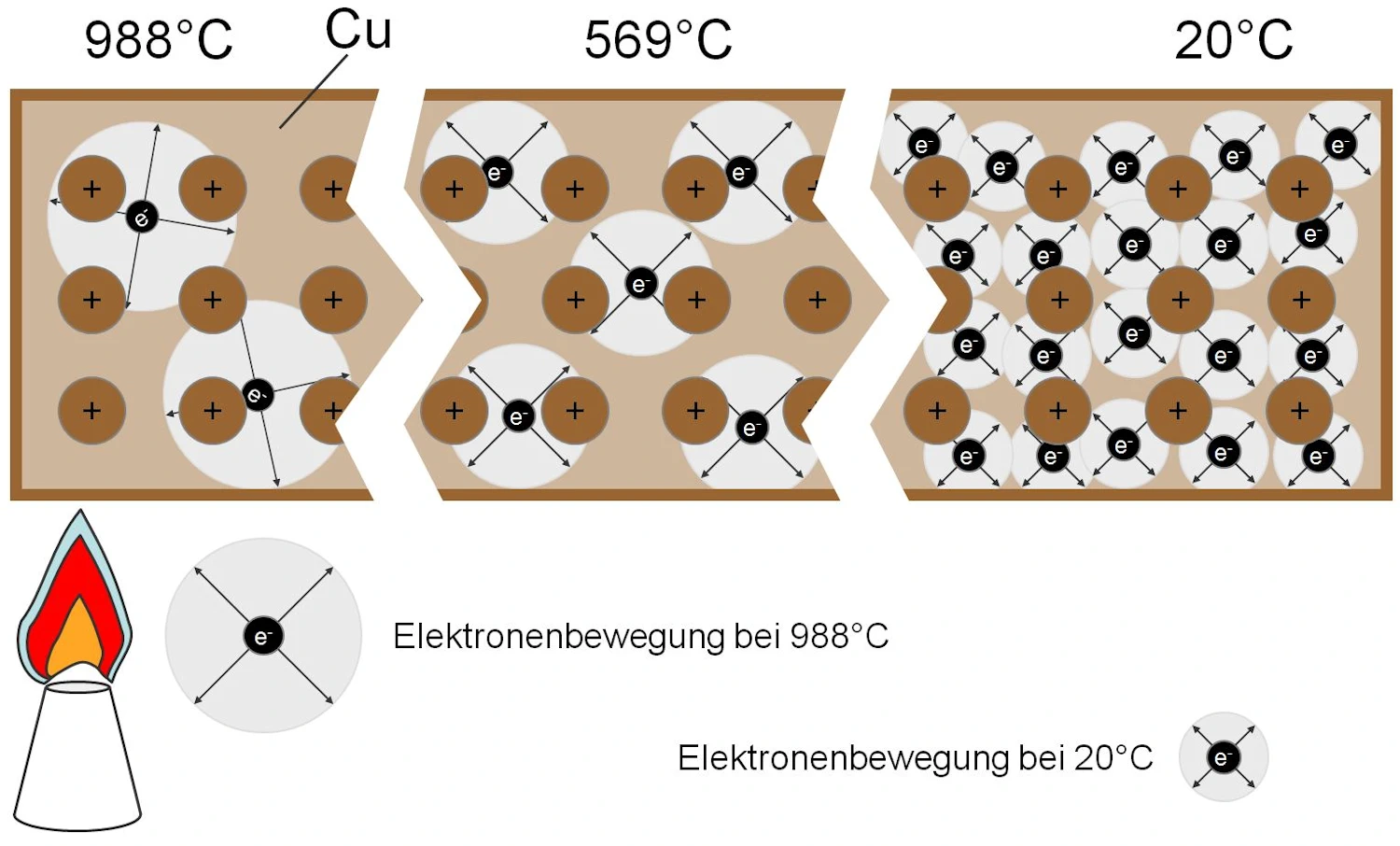
Now heat one end of the ladder.

This increases the range of motion of the free electrons in this region. Because like charges repel each other, the more highly energized electrons “push” the rest toward the cold end.

As a result, there is a shortage of electrons at the heated end and an excess at the cold end. This creates a voltage.

Important to know: The voltage level is mainly influenced by the chemical composition of the wire and the temperature difference!

However, the voltage from a single wire is not enough to generate a signal. Therefore, a second wire is needed. Both wires should be connected at the point with the highest temperature.

The voltage difference between the two wires serves as a signal and is defined as thermoelectric voltage.
A copper conductor that is uniformly warm at room temperature
Electron distribution in a uniformly heated copper conductor at room temperature
Electron distribution in the copper conductor shown above, with one end heated
Thermocouple voltage is the difference between two different thermocouple voltages
Theoretical Measurement of Thermostress Along a Thermocouple