Compensation and Thermal Cables
General
The voltage of thermocouples is defined relative to the zero point. Therefore, thermocouples must not be connected to a standard copper voltage line. Doing so would result in measurement errors. Consequently, special cables must be used for thermocouples. These are commonly referred to as compensation cables.
Their thermoelectric voltage is identical to that of the connected thermocouple up to ~200 °C. For temperatures above 200 °C, the original thermocouple alloys should be used whenever possible.
It is important to note that, as with thermocouples, the materials used in the wires vary. Therefore, care must be taken to ensure correct polarity. To make this easier, the insulation layers are colored to match the thermocouple types.
Variants
Thanks to modern electronics, the wire's resistance is negligible. Therefore, there are practically no requirements regarding the cross-sectional area. Common cross-sectional areas are 0.22 mm² or 0.5 mm².
The design of the insulation depends on local conditions. As a result, there is a very wide variety of designs. Four common materials are:
Polyvinyl chloride (PVC)
It is relatively inexpensive, flexible, and can be used at temperatures up to ~100 °C.
Silicone
Compared to PVC, this material is slightly more expensive, but it offers much greater flexibility and temperature resistance up to ~180 °C.
Polytetrafluoroethylene (Teflon™)
This material is characterized by a very high temperature resistance of ~240 °C. It is also resistant to many chemicals. Compared to PVC and silicone, PTFE is less flexible.
Fiber Optics
In areas with high temperatures (> 200 °C), fiberglass insulation is also used. This type of insulation can withstand temperatures of up to 600 °C. However, it tends to become brittle over time. Consequently, it should only be used for permanently installed cables.
Shielding
Few design choices lead to errors as often as shielding. Shielding is often made of a copper braid that is wrapped around the insulation. In practice, this approach rarely proves effective. Our recommendation would be to avoid shielding altogether and instead run the cables through metal conduits.
If shields are used, it is important that they do not come into contact with the thermocouple. This often leads to leakage currents and unusual behavior.
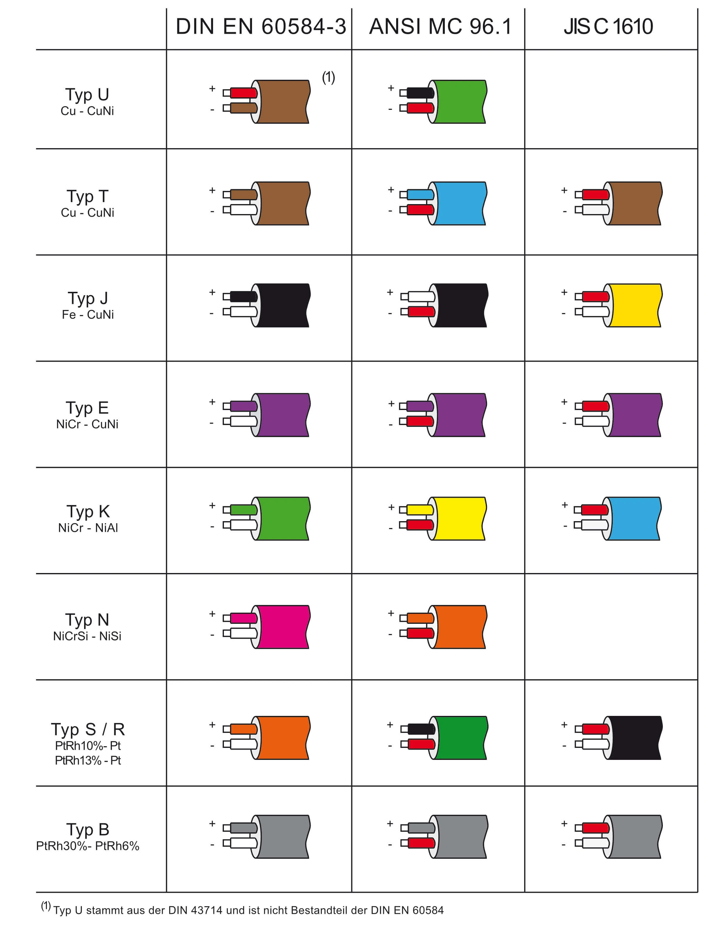
| Type | Positive | Negative |
|---|---|---|
| T | Cu | CuNi |
| J | Fe | CuNi |
| E | NiCr | Ni-Alloy |
| K | NiCr | Ni-Alloy |
| S / R | Cu | Ni-Alloy |
| B | Cu | Cu |
| N | NiCrSi | NiSi |